TM-5-3805-254-14-P-2 - Page 401 of 894
TRUCK SERVICE MANUAL
ENGINE
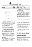
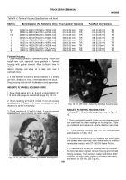
Table 14-3: Injection Timing
Piston
Travel
Push Tube Travel (Inches)
Engine Model
(Inches)
Nominal
Fast
Slow
NT-855-310 (All) NT-855 Series
-0.2032
-0.0360
-0.0340
-0.0380
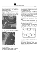
Fig.
148, (Ni1432).
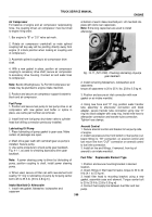
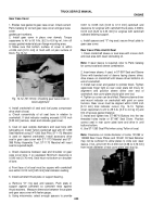
injection timing procedure
3.
Bar crankshaft in rotating direction (2) until piston
follower rod top is opposite 90 deg.
ATC mark on timing
tool.
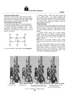
At this point, position push tube indicator on push
rod follower to about 0.020 inch from its inner travel stop.
Zero indicator dial at this point.
4.
Bar crankshaft opposite rotating direction (3) to
position piston follower rod at 45 deg.
BTC.
Note:
Both indicators move in same direction when
cylinder is on proper stroke.
If push tube indicator does
not move same direction as piston indicator, bar
crankshaft one complete revolution to place cylinder on
compression stroke.
5.
Bar crankshaft in direction of rotation until piston
follower rod is almost in contact with indicator stem.
Gently move crankshaft to position piston indicator to
0.0032 inch before 0.
This position is actually 0.2032
inch before 0, since the indicator will have receded (hand
will have gone around twice) over 0.200 inch as the
crankshaft was moved to 45 deg.
BTC.
Since exact
reading in ten-thousandths must be estimated, exercise
care in bringing piston travel indicator to reading.
6.
Read push tube travel indicator.
It should read the
number of thousandths before zero that is called for in
Table 14-3.
Notice that a range of about 0.004 inch is
within specification.
Note:
Never make a change in cam follower gaskets for
timing purposes before making following checks:
a.
Be sure cam follower housing capscrews are
tightened to 30 to 35 ft-lbs [4.1 to 4.8 kg ml torque.
b.
Recheck indicator positioning.
Be sure indicators are
not bottoming or binding.
c.
Carefully recheck top center position.
Be sure each
step is carried out as described.
7.
If push tube travel is greater than limits indicated in
Table 14-3, engine timing is slow; if push tube travel is
less, timing is fast.
Injection timing may be advanced or
retarded by adding or removing cam follower gaskets.
Remove gasket on right hand engine to retard timing.
Add gaskets on left hand engines to retard timing.
Note:
If required, an extra-thick gasket should be used
when needed instead of several thin gaskets.
Injectors
1.
Lubricate the injector body "O" rings with light coat of
clean lubricating oil.
2.
Start the injector assembly into bore, from intake side
of engine, injectors are to be placed with filter screen at
twelve o’clock, guide by hand until injector is aligned.
3.
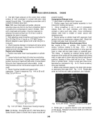
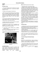
Place ST-448 Valve Spring Compressor on top of
injector plunger coupling and "seat" injector by giving a
quick, hard push.
4.
Place hold-down plate over injector body with
counterbore up.
Start hold-down capscrews.
Do not
tighten.
5.
Carefully insert injector plunger link.
Torque hold-
down capscrews to 11 to 12 ft-lbs [1.5 to 1.7 kg ml
in 4
ft-lb [0.6 kg m] increments.
Fuel Fittings And Lines
Coat fuel fittings with sealer.
Inlet and drain fittings may be installed either in front of
No.
1 head or rear of No.
3 head as used.
Connect
tubing to appropriate fitting.
VALVE CROSSHEAD ADJUSTMENT
1.
Position crossheads over guides with adjusting screw
toward water manifold.
Loosen adjusting screw locknut,
back adjusting screw off one turn.
Note:
Engines using Jacobs Brake use special
crossheads on exhaust side of head.
See Group 20.
397
Back to Top

