TM-5-3805-254-14-P-2 - Page 403 of 894
TRUCK SERVICE MANUAL
ENGINE
Air Compressor
For balance of engine and air compressor reciprocating
force, the coupling driven air compressor must be timed
to engine firing order.
1. Bar engine to "B" or "2-5" valve set mark.
2. Rotate air compressor crankshaft so male splined
coupling half key-way will be pointing directly away from
engine (3 o’clock position when looking at coupling end
of compressor).
3. Assemble splined coupling to air compressor drive
shaft.
4. With a new gasket in place, position air compressor
coupling to accessory drive shaft; secure air compressor
to accessory drive housing. Connect air and water lines
to compressor.
Note:
Bendix Westinghouse Tu-Flo 500 Compressor air
intake may be plumbed to engine intake manifold,
5. Position and secure air compressor support bracket to
block and air compressor.
Fuel Pump
1. Position and secure fuel pump to fuel pump drive or air
compressor with new gasket and buffer or spline in
place, use same part number as removed.
2. Install line from fuel pump shut-down valve to cylinder
head fuel drilling connection previously installed.
Lubricating Oil Pump
1. Place lubricating oil pump gasket to gear case. Make
certain oil passages are open.
2. Mesh drive gear teeth with camshaft gear as pump is
installed. Secure pump.
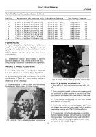
3. Use same procedure to check pump gear backlash,
Fig. 4-1 1, as used for checking accessory drive gear
backlash.
Note:
If power steering pump is driven by lubricating oil
pump, position coupling to shaft, install power steering
pump.
4. When used, secure oil filter can with new element and
sealing "O" ring to lubricating oil pump by torquing center
bolt to 25 to 35 ft-lb. [3.5 to 4.8 kg m] .
Intake Manifold Or Aftercooler
1. Install new gasket, flatwasher, lockwasher and
capscrew
at bottom of each intake manifold port. Lift manifold into
place with slots over capscrews.
Note:
Extra long capscrews are used to install
aftercooler.
Back to Top

