TM-5-3805-254-14-P-2 - Page 400 of 894
TRUCK SERVICE MANUAL
ENGINE
Compression Release Shaft
Install new "0" ring over shaft.
Insert shaft into cylinder
block and secure at rear end of block with copper washer
and lockscrew.
Coat expansion plug with sealant, install
plug in counterbore at rear of block, until it seats.
Cam Followers And Push Tubes
1.
Install cam follower gaskets.
It may be necessary to
add or remove gaskets to obtain correct injection timing.
2.
Position cam follower assembly to block.
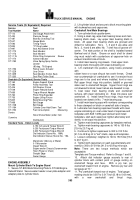
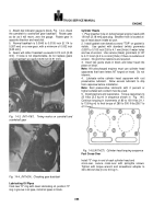
Torque
capscrews in sequence as shown in Fig.
14-6 in
increment of 15 to 20 ft-lbs [2.1 to 2.8 kg m] to 30 to 35
ft-lbs [4.1 to 4.8 kg ml .
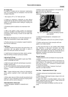
Fig.
146, (N114236).
Cam follower torquing
sequence
3.
install push tubes.
Injector push tube is largest and
fits in middle socket.
On engines equipped with
compression release, exhaust push tube is equipped with
collar to match with milled lift of compression release.
On engines without compression release, intake and
exhaust tubes are identical.
Timing The Engine
Use ST-593 to obtain precise timing of push tube travel
with piston travel.
The travel readings for engine model
must be as listed in Table 14-3.
Adjustments to timing
are made by altering thickness of cam follower housing
gaskets.
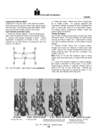
1.
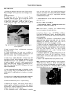
Position ST-593 Timing Tool in injector sleeve.
Engage rod of push rod indicator in injector push tube
socket.
Secure tool in place by tightening knurled hold-
downs evenly by hand.
Be sure tool is straight in the
cylinder.
Fig.14-7.
Note:
Each of the two dial indicators used in timing
engine must have total travel of at least 0.250 inch [6.35
mml .
2.
Loosen both indicator supports to prevent damage.
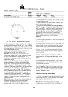
Bar engine crankshaft to bring piston to top center.
Position piston indicator to compress indicator stem to
within 0.010 inch of inner travel stop.
Carefully bar
crankshaft to bring piston to exactly top center (1, Fig.
14-8).
Zero the indicator dial at this point.
Back to Top

