TM-5-3805-254-14-P-2 - Page 385 of 894
TRUCK SERVICE MANUAL
ENGINE
WATER PUMP/I D LER (FFC SERIES-ECCENTRIC)
DISASSEMBLY AND INSPECTION
1.
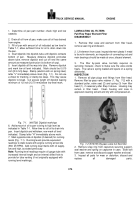
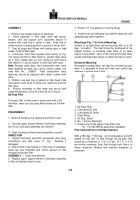
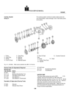
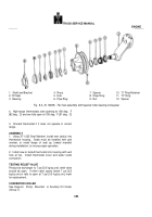
Remove pulley (1, Fig.
8-1) and impeller (12) using
ST-647 puller or equivalent.
2.
Remove ceramic seat and rubber seal (13), large oil
seal (4) and snap ring (5), discard seals.
3.
Support pulley end of pump body (10) and press
bearing and shaft assembly from body.
4.
Using both halves of ST-1114 Bearing Puller installed
around bearing spacer in the grease channel, press shaft
through outer bearing (6) and bearing spacer (8).
5.
Remove snap ring (2) securing inner bearing (7),
supporting bearing race, press shaft from bearing.
6.
Remove carbon face seal (11) and small oil seal (9)
from water pump body (10); discard seals.
7.
1 nspect bearings and spacer for roughness and
wear.
8.
Inspect water pump impeller; replace if cracked or
corroded to extent that it will retard coolant circulation.
9.
Measure impeller/pulley bore and shaft diameter.
There should be a minimum of 0.001 inch [0,03 mm]
press-fit between shaft and bore.
Inspect shaft for
straightness and galling on press fit diameter surfaces.
10.
Inspect pulley grooves for wear, water pump body for
cracks, possible damage from bearing spinning, and that
"weep" hole is open.
Repair or replace parts as
necessary.
11.
Inspect wear sleeve (3) on pulley (if used).
If
grooves are visible, remove sleeve as follows:
a.
Grind a 15 deg.
angle on end of a 3/16 inch straight
shank round punch.
b.
Secure pulley in vise.
Do not tighten too tight,
excessive pressure could crack pulley.
c.
Using punch, drive sleeve from pulley hub by placing
punch through puller holes in pulley; discard sleeve.
d.
Install new sleeve with a suitable mandrel.
ASSEMBLY
1.
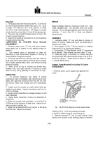
Lubricate shaft (14, Fig.
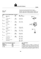
8-1) and using ST-658
Mandrel seated on inner race, press inner bearing (7)
over shaft (14) until it bottoms on shaft shoulder.
Install
snap ring (2) and bearing spacer (8).
2.
Using ST-658 Mandrel seated on inner race of outer
bearing (6), press bearing on shaft (14) until it seats
against bearing spacer (8).
Check both bearings for free
rotation.
3.
Install small oil seal (9), if used (idler pulley type
body), into body, using ST-1191-2 Seal Mandrel, with lip
of seal opposite impeller end.
4.
Using ST-659 Mandrel, install new carbon face seal
(11), into body (10) until seal bottoms in bore.
Keep seal
face free of grease or other foreign material.
5.
Press shaft and bearing assembly into water pump
body (10) using ST-658 Mandrel.
Do not support body
on thin sections of impeller cavity.
Install retaining ring
(5).
6.
Install large oil seal (4), if used (idler pulley type body),
into body using ST-1 191-3 Seal Mandrel.
7.
Install new ceramic seat (with dimples on face away
from carbon face seal) on shaft; install rubber seal on
shaft against ceramic seat (with flat side toward impeller
end of shaft).
Lubricate bore with a solution of clean
soap water or liquid soap to ease installation onto shaft.
8.
Support water pump on pulley end of shaft and press
impeller on shaft, maintaining 0.020 to 0.040 inch [0.51 fo
1.02 mm] clearance between impeller and cavity.
9.
Support water pump assembly on impeller end of
shaft (not on impeller) and press pulley on shaft until
pulley hub is flush with shoulder on shaft.
Install locknut
and washer (if used), tighten to 90 to 100 ft-lbs [12.5 to
13.8 kg m] torque.
10.
Install new grease and relief fittings if required.
Fill
1/2 to 2/3 full with grease.
See Group 18 for type grease.
11.
Check assembly for freedom of rotation.
Idler Pulley Assembly
DISASSEMBLY AND INSPECTION
1.
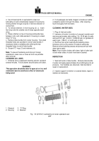
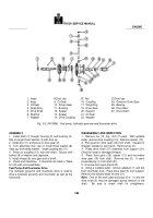
Remove spacer from shaft.
Remove "O" ring, oil seal
and snap ring.
2.
Remove shaft and bearing assembly from pulley.
It
may be necessary to remove pipe plug and use a small
punch to knock shaft and bearing assembly from pulley.
3.
Inspect idler bearing for roughness and wear, if
required, press shaft from bearing, inspect shaft for
straightness or galling on bearing surface and mutilated
threads.
4.
Inspect spacer for excessive wear or grooves in oil
seal area.
If grooves are visible replace spacer.
5.
Inspect pulley grooves for wear.
Replace parts as
necessary.
ASSEMBLY
1.
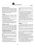
Lubricate shaft and using a suitable mandrel seated
on
381
Back to Top

