TM-5-3805-264-13-P - Page 228 of 660
REMOVAL
NOTE
•
Wires should be tagged before disconnecting (WP 0072).
•
Note location of tiedown straps and routing of wiring harness prior to removal to
aid in installation.
1.
Remove tiedown straps and discard.
2.
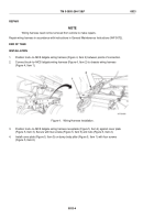
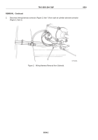
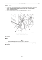
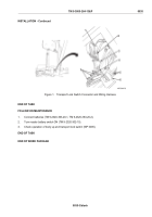
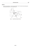
Disconnect transport lock switch connector (Figure 1, Item 1) from wiring harness connector
(Figure 1, Item 2).
3.
Disconnect two wiring harness leads (Figure 1, Item 5) from body up switch (Figure 1, Item 6).
4.
Disconnect wiring harness connector (Figure 1, Item 4) from chassis wiring harness connector (Figure 1,
Item 3) and remove wiring harness (Figure 1, Item 7).
END OF TASK
REPAIR
NOTE
Wiring harness need not be removed from vehicle to make repairs.
Repair wiring harness in accordance with instructions in General Maintenance Instructions (WP 0072).
END OF TASK
INSTALLATION
1.
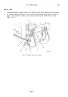
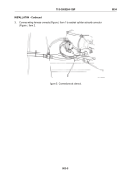
Connect wiring harness connector (Figure 1, Item 4) to chassis wiring harness connector (Figure 1, Item 3).
2.
Connect two wiring harness leads (Figure 1, Item 5) to body up switch (Figure 1, Item 6).
3.
Connect transport lock switch connector (Figure 1, Item 1) to wiring harness connector (Figure 1, Item 2).
4.
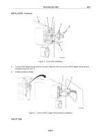
Secure wiring harness (Figure 1, Item 7) with new tiedown straps.
TM 5-3805-264-13&P
0035
0035-2
Back to Top

