TM-5-5420-202-20-2 - Page 501 of 734
TM 5-5420-202-20-2
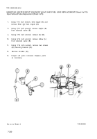
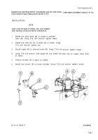
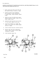
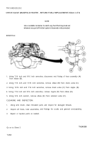
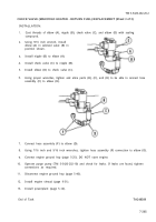
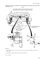
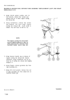
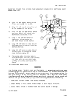
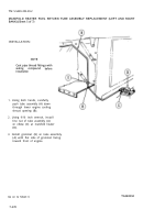
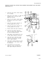
MANIFOLD HEATER FUEL RETURN TUBE ASSEMBLY REPLACEMENT (LEFT AND RIGHT
BANK) (Sheet 1 of 7)
PROCEDURE INDEX
PROCEDURE
I
PAGE
------ ---- -
--— --— ———
. .— — — ___ -—.— ________ ____ ._ ______ ___
Removal
7-266
Cleaning and Inspection
7-269
Installation
7-270
------ -——- ___
——-_ _ _
.—
---—— .
. ______ ____ . .
TOOLS: 5/16 in. combination box and open end wrench
1/2 in. combination box and open end wrench
9/16 in. combination box and open end wrench (2 required)
1/2 in. socket with 1/2 in. drive
8 in. adjustable wrench
Flat-tip screwdriver
Hammer, 2 lb ball peen
Ratchet with 1/2 in. drive
SUPPLIES:
Clean rags (Item 12, Appendix D)
Gloves (Item 69, Appendix D)
Sealing compound (Item 27, Appendix D)
Goggles (Item 70, Appendix D)
Dry cleaning solvent (Item 55, Appendix D)
Container
PERSONNEL: T
W O
PRELIMINARY PROCEDURES:
Remove powerplant (page 5-2)
Remove engine shroud (page 9-30)
CAUTION
When removing or installing fuel lines, care must be taken not to
damage fittings and threads or twist or distort fuel lines or hoses.
NOTE
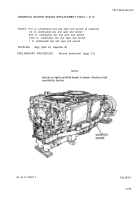
There are two manifold heater fuel return tube assemblies,
one for the left bank and one for the right bank. Removal
and installation procedures for both tube assemblies are
similar. This procedure covers the right bank tube assembly.
Go on to Sheet 2
7-266
TA248390
Back to Top

