TM-5-5420-202-20-3 - Page 377 of 1060
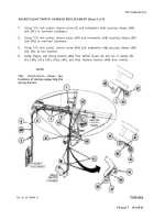
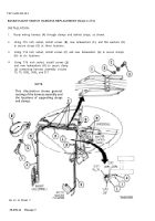
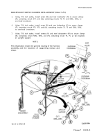
BASKET/CONTROL PANEL ACCESSORIES HARNESS REPLACEMENT (Sheet 4 of 5)
INSTALLATION:
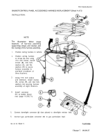
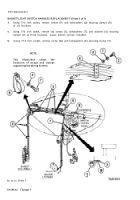
NOTE
TM 5-5420-202-20-3
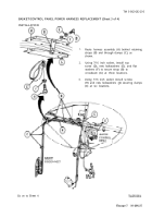
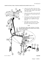
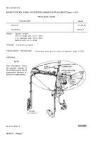
The
illustration
below
shows
locations
of harness assembly
supporting straps and clamps and
the routing of the harness assembly.
1.
2.
3.
4.
5.
6.
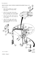
Position wiring harness in vehicle.
Position wiring harness
in straps (A) and, using
7/16 inch socket, install
screws (B), new lock-
washers (C), and flat
washers (D) to secure
harness assembly to
overhead crossbeam at
three locations.
Using 7/16 inch socket,
and extension, install clamps
(E), screws (F), and new lock-
washers (G) securing harness
assembly at eight locations.
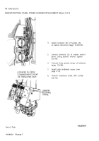
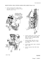
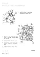
Install connector
(H) at basket discon-
nect (page 10-296.71).
Connect domelight connector (J) (two places) to domelight resistor lead.
Connect gas particulate connector (K) to gas particulate lead.
Go on to Sheet 5
5-39
Change 7
10-296.37
Back to Top

