TM-5-5420-202-20-3 - Page 509 of 1060
TM 5-5420-202-20-3
SHIFTING CONTROL AND RELATED PARTS REPAIR AND REPLACEMENT (Sheet 11 of 14)
20.
21.
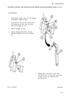
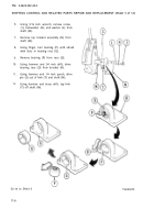
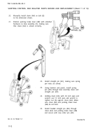
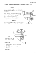
Manually install clevis (AA) on bolt (E)
to the dimension shown.
Position parking brake lever (AB) with attached
hardware on base assembly (F), making sure
that clevis (AA) is alined correctly.
22.
23.
24.
25.
Install straight pin (AC), making sure spring
pin holes are alined.
Using hammer and punch, install spring
pin (AD) through base assembly clevis and
straight pin (AC).
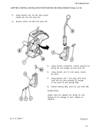
Holding clevis (AA) with 3/4 inch open end
wrench, use 1/2 inch open end wrench to
tighten nut (G) against clevis (AA). Make
sure clevis (AA) and parking brake lever
(AB) do not bind.
Install headed straight pin (AE) through
clevis (AA) and parking brake lever (AB)
and secure with new cotter pin (AF).
TA249279
Go on to Sheet 12
11-12
Back to Top

