TM-5-5420-202-20-3 - Page 605 of 1060
TM 5-5420-202-20-3
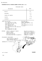
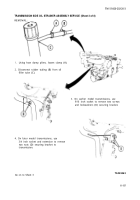
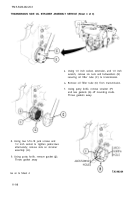
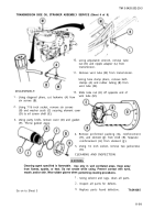
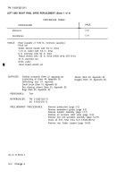
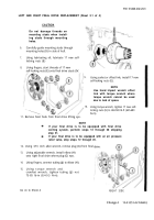
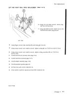
LEFT AND RIGHT FINAL DRIVE REPLACEMENT (Sheet 1 of 4)
PROCEDURE INDEX
PROCEDURE
PAGE
Removal
12-2
Installation
12-4
TOOLS:
Hoist (capable of 1100 lb. minimum capacity)
Pinch bar
Socket wrench handle with 3/4 in. drive
1-1/2 in. socket with 3/4 in. drive
8 in. extension with 3/4 in. drive
Torque wrench with 3/4 in. drive (0-600 lb-ft) (813 N·m)
36 in. extension bar
Knife, putty
Hand impact wrench set
SUPPLIES:
Sealing compound (Item 27, Appendix D)
Gloves (Item 69, Appendix D)
Goggles (Item 70, Appendix D).
Lubricating oil (Item 44, Appendix D)
Self-locking nuts (17 required)
Small brush (Item 10, Appendix D)
Dry cleaning solvent (Item 55, Appendix D)
Rags (Item 65, Appendix D)
PERSONNEL:
Two
REFERENCES:
TM 5-5420-202-10
LO 5-5420-202-12
PRELIMINARY PROCEDURES:
Remove powerplant (page 5-2)
Remove powerplant guides (page 6-3)
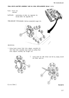
Remove adapter assembly (page 12-7)
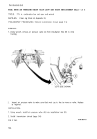
Remove air pressure relief valve (page 12-6)
Remove hub and sprockets assembly (page 14-70)
Drain oil from final drive (LO 5-5420-202-12)
Remove rear fender support (page 16-69)
Go on to Sheet 2
12-2
Change 4
Back to Top

