TM-9-2320-272-23-2 - Page 1152 of 1417
BLOWER MOTOR SWITCH INSTALLATION - Continued
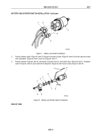
3.
Install blower motor switch (Figure 4, Item 2) on instrument panel (Figure 4, Item 6), with lockwasher
(Figure
4,
Item
4), and nut (Figure 4, Item 3).
4.
Position lever (Figure 4, Item 2) on blower motor switch (Figure 4, Item 5) with pointing edge placed in OFF
position and install with screw (Figure 4, Item 1).
M9429DAA
6
5
1
2
3
4
Figure 4.
Blower Motor Switch Installation.
END OF TASK
BATTERY AND STARTER SWITCH REMOVAL
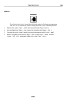
1.
Remove screw (Figure 5, Item 9), lockwasher (Figure 5, Item 8), switch lever (Figure 5, Item 1), felt washer
(Figure 5, Item 2), and washer (Figure 5, Item 3) from battery switch (Figure 5, Item 5). Discard lockwasher.
2.
Remove nut (Figure 5, Item 7) and lockwasher (Figure 5, Item 4) from instrument cluster (Figure 5, Item 6) and
pull switch (Figure 5, Item 5) from behind instrument cluster (Figure 5, Item 6). Discard lockwasher.
5
6
7
8
9
1
2
3
4
M9514DAA
Figure 5.
Battery and Switch Removal.
TM 9-2320-272-23-2
0307
0307-3
Back to Top


