TM-9-2320-272-23-2 - Page 473 of 1417
PRELIMINARY DISCONNECTIONS - Continued
49.
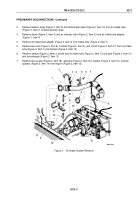
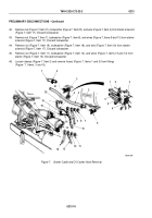
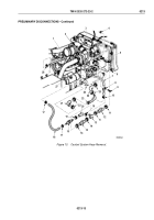
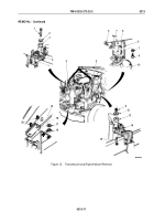
Remove nut (Figure 10, Item 4), screw (Figure 10, Item 9), clamp (Figure 10, Item 8), and hose
(Figure
10,
Item
7) from bracket (Figure 10, Item 5).
50.
Remove clamps (Figure 10, Items 10 and 28) and hose (Figure 10, Item 7) from surge tank fitting
(Figure
10,
Item 1) and tube (Figure 10, Item 23).
NOTE
Perform Steps (51) and (52) for internal bypass systems.
51.
Remove two clamps (Figure 10, Item 17) and hose (Figure 10, Item 18) from fitting (Figure 10, Item 27) and
thermostat canister (Figure 10, Item 16).
52.
Remove two clamps (Figure 10, Item 19), thermostat canister (Figure 10, Item 16), and hose
(Figure
10,
Item
20) from tube (Figure 10, Item 13).
NOTE
Perform Step (53) for external bypass systems.
53.
Remove two clamps (Figure 10, Item 17) and hose (Figure 10, Item 18) from fitting (Figure 10, Item 3) and
tube (Figure 10, Item 13).
54.
Remove two clamps (Figure 10, Item 11), hump hose (Figure 10, Item 12), two clamps (Figure 10, Item 14),
hump hose (Figure 10, Item 15), and tube (Figure 10, Item 13) from outlet tube (Figure 10, Item 6) and
transmission oil cooler (Figure 10, Item 26).
55.
Remove two clamps (Figure 10, Item 25), elbow (Figure 10, Item 24), two clamps (Figure 10, Item 22), elbow
(Figure 10, Item 21), and tube (Figure 10, Item 23) from outlet port (Figure 10, Item 2) and transmission oil
cooler (Figure 10, Item 26).
TM 9-2320-272-23-2
0213
0213-12
Back to Top

