TM-9-2320-272-23-2 - Page 475 of 1417
PRELIMINARY DISCONNECTIONS - Continued
56.
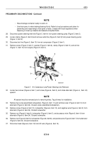
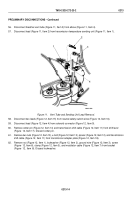
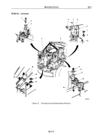
Disconnect breather vent tube (Figure 11, Item 3) from elbow (Figure 11, Item 4).
57.
Disconnect lead (Figure 11, Item 2) from transmission temperature sending unit (Figure 11, Item 1).
1
2
3
4
M9261-1DAA
Figure 11.
Vent Tube and Sending Unit Lead Removal.
58.
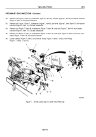
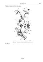
Disconnect two leads (Figure 12, Item 15) from neutral safety switch wires (Figure 12, Item 16).
59.
Disconnect lead (Figure 12, Item 4) from solenoid connector (Figure 12, Item 9).
60.
Remove cotter pin (Figure 12, Item 14) and transmission shift cable (Figure 12, Item 11) from shift lever
(Figure
12, Item 17). Discard cotter pin.
61.
Remove two nuts (Figure 12, Item 10), u-bolt (Figure 12, Item 13), spacer (Figure 12, Item 12), and transmission
shift cable (Figure 12, Item 11) from transmission adapter plate (Figure 12, Item 18).
62.
Remove nut (Figure 12, Item 1), lockwasher (Figure 12, Item 2), ground wire (Figure 12, Item 3), screw
(Figure
12, Item 6), clamp (Figure 12, Item 5), and modulator cable (Figure 12, Item 7) from bracket
(Figure
12,
Item
8). Discard lockwasher.
TM 9-2320-272-23-2
0213
0213-14
Back to Top

