TM-9-2320-272-23-2 - Page 469 of 1417
PRELIMINARY DISCONNECTIONS - Continued
NOTE
•
Have drainage container ready to catch oil.
•
Use drain pans to retain leaking/draining fluids. Refer to local procedures and plans for
preventing and responding to fluid spills or leaks. Comply with local regulations when
disposing of clean up material and leaked and spilled fluids.
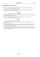
28.
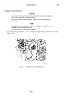
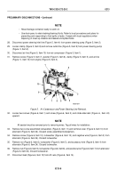
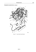
Disconnect power steering inlet line (Figure 5, Item 4) from power steering pump (Figure 5, Item 2).
29.
Loosen clamp (Figure 5, Item 8) and remove outlet line (Figure 5, Item 9) from power steering pump
(Figure
5, Item 2).
30.
Disconnect air line (Figure 5, Item 10) from air compressor (Figure 5, Item 1).
31.
Remove screw (Figure 5, Item 7), washer (Figure 5, Item 6), clamp (Figure 5, Item 5), and air line
(Figure
5,
Item 10) from engine (Figure 5, Item 3).
1
10
9
8
7
6
5
4
3
2
M9258-1DAA
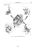
Figure 5.
Air Compressor and Power Steering Line Removal.
32.
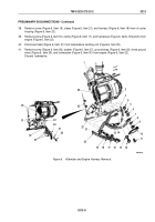
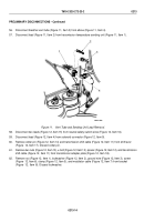
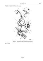
Loosen two screws (Figure 6, Item 1) and screw (Figure 6, Item 2), and rotate alternator (Figure
6,
Item
24)
upward.
NOTE
All sealant must be removed prior to removing wires. Tag all wires for installation.
33.
Remove two screw assembled lockwashers (Figure 6, Item 11) and terminal cover (Figure 6, Item 10) from
alternator (Figure 6, Item 24). Discard screw assembled lockwashers.
34.
Remove screw (Figure 6, Item 12), lockwasher (Figure 6, Item 13), and negative wire (Figure 6, Item 3) from
alternator (Figure 6, Item 24). Discard lockwasher.
35.
Remove nut (Figure 6, Item 6), lockwasher (Figure 6, Item 5), and accessory wire (Figure 6, Item 4) from
alternator (Figure 6, Item 24). Discard lockwasher.
36.
Remove nut (Figure 6, Item 9), lockwasher (Figure 6, Item 8), and positive wire (Figure 6, Item 7) from alternator
(Figure 6, Item 24). Discard lockwasher.
37.
Disconnect lead (Figure 6, Item 15) from AC wire (Figure 6, Item 14).
TM 9-2320-272-23-2
0213
0213-8
Back to Top

