TM-9-2320-272-23-2 - Page 483 of 1417
INSTALLATION - Continued
10.
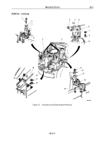
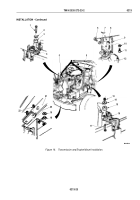
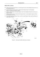
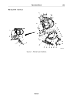
Install two screws (Figure 16, Item 17), isolators (Figure 16, Item 15), washers (Figure 16, Item 14), and
locknuts (Figure 16, Item 13) on left engine mounting bracket (Figure 16, Item 16). Finger-tighten locknuts.
11.
Install two isolators (Figure 16, Item 3), washers (Figure 16, Item 2), and screws (Figure 16, Item 1) on right
engine mounting bracket (Figure 16, Item 4). Finger-tighten screws.
12.
Install backing plate (Figure 16, Item 20) on crossmember (Figure 16, Item 21) and screws
(Figure
16,
Item
22) with two washers (Figure 16, Item 19) and locknuts (Figure 16, Item 18). Finger-tighten
locknuts.
13.
Install transmission mounting bracket (Figure 16, Item 9) on transmission (Figure 16, Item 12) with two
lockwashers (Figure 16, Item 7) and screws (Figure 16, Item 6).
14.
Raise transmission (Figure 16, Item 12) and install transmission mounting brackets (Figure 16, Item 9) on
isolator (Figure 16, Item 8) with lockwasher (Figure 16, Item 10) and screw (Figure 16, Item 11).
15.
Tighten locknuts (Figure 16, Item 13) 120 to 140 lb-ft (163 to 190 N·m).
16.
Tighten screws (Figure 16, Item 1) 120 to 140 lb-ft (163 to 190 N·m).
17.
Tighten locknuts (Figure 16, Item 18) 75 to 85 lb-ft (102 to 115 N·m).
18.
Remove lifting device and utility chain from two engine lifting brackets (Figure 16, Item 5).
TM 9-2320-272-23-2
0213
0213-22
Back to Top

