TM-9-2320-272-23-2 - Page 491 of 1417
INSTALLATION - Continued
NOTE
Wrap all male pipe threads with antiseize tape before installation.
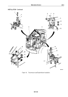
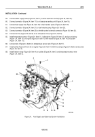
44.
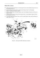
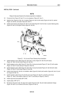
Connect air line (Figure 22, Item 10) on air compressor (Figure 22, Item 1).
45.
Install air line (Figure 22, Item 10) on engine (Figure 22, Item 3) with clamp (Figure 22, Item 5), washer
(Figure
22, Item 6), and screw (Figure 22, Item 7).
46.
Install power steering inlet (Figure 22, Item 4) and outlet (Figure 22, Item 9) lines on power steering pump
(Figure 22, Item 2) and tighten clamp (Figure 22, Item 8).
1
10
9
8
7
6
5
4
3
2
M9268DAA
Figure 22.
Air Line and Power Steering Hose Installation.
47.
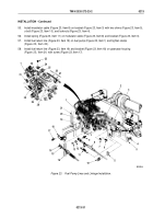
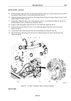
Install emergency stop cable (Figure 23, Item 26) on screw (Figure 23, Item 25) with sleeve
(Figure
23,
Item
24) and screw (Figure 23, Item 23).
48.
Install emergency stop cable (Figure 23, Item 26) on fuel pump bracket (Figure 23, Item 22) with washer
(Figure
23, Item 31) and cotter pin (Figure 23, Item 30).
49.
Install emergency stop cable (Figure 23, Item 26) on fuel pump bracket (Figure 23, Item 28) with clamp
(Figure
23, Item 27) and screw (Figure 23, Item 29).
50.
Install screw (Figure 23, Item 9) on modulator cable (Figure 23, Item 8) with washer (Figure 23, Item 12) and
nut (Figure 23, Item 13).
51.
Install modulator cable (Figure 23, Item 8) and screw (Figure 23, Item 9) on throttle control lever
(Figure
23,
Item 2) with washer (Figure 23, Item 7) and cotter pin (Figure 23, Item 6).
52.
Install surge tank and bracket (WP
0279).
53.
Install radiator (WP
0277).
54.
Pull sleeve (Figure 23, Item 15) away from socket (Figure 23, Item 16) and install accelerator linkage
(Figure
23, Item 14) on throttle control lever (Figure 23, Item 2).
TM 9-2320-272-23-2
0213
0213-30
Back to Top

