TM-9-2320-272-23-2 - Page 489 of 1417
INSTALLATION - Continued
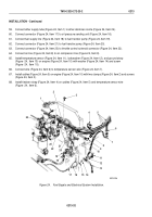
33.
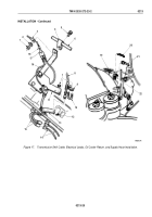
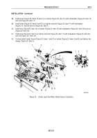
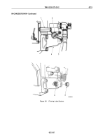
Install lockwasher (Figure 21, Item 3), three ground wires (Figure 21, Item 7), and ground strap
(Figure
21,
Item
4) on engine (Figure 21, Item 2) with washer (Figure 21, Item 6) and screw
(Figure
21,
Item
5).
34.
Route lead (Figure 21, Item 8) over engine (Figure 21, Item 2) and connect to temperature sending unit
(Figure
21,
Item
1).
35.
Connect lead (Figure 21, Item 22) to AC wire (Figure 21, Item 21).
NOTE
Ensure terminals are clean prior to installing wires.
36.
Install accessory wire (Figure 21, Item 12) on alternator (Figure 21, Item 31) with lockwasher
(Figure
21,
Item
13) and nut (Figure 21, Item 14). Tighten nut 20 to 25 lb-ft (2 to 3 N·m).
37.
Install negative wire (Figure 21, Item 11) on alternator (Figure 21, Item 31) with lockwasher
(Figure
21,
Item
23) and screw (Figure 21, Item 20). Tighten screw 82 to 102 lb-ft (9 to 12 N·m).
38.
Install positive wire (Figure 21, Item 15) on alternator (Figure 21, Item 31) with lockwasher
(Figure
21,
Item
16) and nut (Figure 21, Item 17). Tighten nut 45 to 55 lb-ft (5 to 6 N·m).
NOTE
Completely seal wires and inside of terminal cover with silicone rubber adhesive.
39.
Install terminal cover (Figure 21, Item 18) on alternator (Figure 21, Item 31) with two screw assembled
lockwasher (Figure 21, Item 19).
40.
Install harnesses (Figure 21, Items 26 and 28) and clamp (Figure 21, Item 25) on engine (Figure 21, Item 2)
with screw (Figure 21, Item 24).
41.
Install harness (Figure 21, Item 26) and clamp (Figure 21, Item 29) on oil cooler housing (Figure 21, Item 30)
with screw (Figure 21, Item 27).
42.
Rotate alternator (Figure 21, Item 31) downward and tighten screw (Figure 21, Item 9).
43.
Tighten two screws (Figure 21, Item 10) 35 lb-ft (47 N·m).
TM 9-2320-272-23-2
0213
0213-28
Back to Top

