TM-9-2320-272-23-2 - Page 494 of 1417
INSTALLATION - Continued
69.
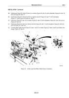
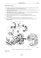
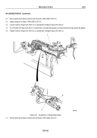
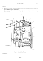
Install two spacers (Figure 25, Item 12) and bracket (Figure 25, Item 13) on engine (Figure 25, Item 10) with
two washers (Figure 25, Item 17) and screws (Figure 25, Item 16).
70.
Install air intake tube (Figure 25, Item 6) on turbocharger (Figure 25, Item 9) and pipe (Figure 25, Item 11) with
clamps (Figure 25, Items 7 and 14).
71.
Install bracket (Figure 25, Item 4) and u-bolt (Figure 25, Item 15) on air intake tube (Figure 25, Item 6) and
bracket (Figure 25, Item 13) with two nuts (Figure 25, Item 5).
72.
Install air intake tube adapter (Figure 25, Item 3) on air intake tube (Figure 25, Item 6).
73.
Install air indicator tube (Figure 25, Item 1) on air intake tube adapter (Figure 25, Item 3) with clamp
(Figure
25, Item
2).
74.
Connect tachometer cable (Figure 25, Item 18) on tachometer drive (Figure 25, Item 19).
75.
Secure tachometer cable (Figure 25, Item 18) to air intake tube (Figure 25, Item 6) with tiedown strap
(Figure
25, Item 8).
1
2
3
4
5
6
7
9
19
18
10
11
1
12
13
15
14
16
17
18
8
M9270DAA
Figure 25.
Air Intake, Tachometer Cable, and Drive Installation.
END OF TASK
TM 9-2320-272-23-2
0213
0213-33
Back to Top

