TM-9-2320-272-23-2 - Page 492 of 1417
INSTALLATION - Continued
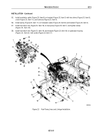
55.
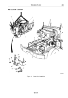
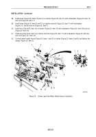
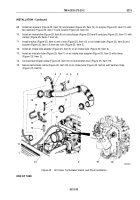
Install modulator cable (Figure 23, Item 8) on bracket (Figure 23, Item 3) with two shims (Figure 23, Item 5),
u-bolt (Figure 23, Item 10), and locknuts (Figure 23, Item 4).
56.
Install spring (Figure 23, Item 11) on modulator cable (Figure 23, Item 8) and bracket (Figure 23, Item 3).
57.
Install fuel return line (Figure 23, Item 19) on fuel pump (Figure 23, Item 1) and tighten clamp
(Figure
23,
Item
20).
58.
Install fuel return line (Figure 23, Item 19) and bracket (Figure 23, Item 18) on gearcase housing
(Figure
23,
Item 21) with screw (Figure 23, Item 17).
2
3
5
4
5
10
11
13
12
8
9
7
6
14
15
16
17
18
19
20
21
1
28
29
30
26
25
24
23
22
1
31
27
M9269DAA
Figure 23.
Fuel Pump Lines and Linkage Installation.
TM 9-2320-272-23-2
0213
0213-31
Back to Top

