TM-9-2320-272-23-2 - Page 645 of 1417
INSTALLATION
NOTE
Wrap male pipe threads with antiseize tape before installation.
1.
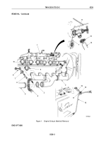
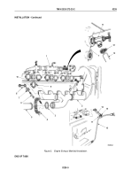
Install intake manifold (Figure 4, Item 3) and three gaskets (Figure 4, Item 5) on cylinder heads
(Figure
4,
Item
1) with eight screw-assembled washers (Figure 4, Item 4). Tighten screw-assembled washers
25 to 30 lb-ft (34 to 41 N·m).
NOTE
Perform Step (2) only if clamps were removed previously.
2.
Install two clamps (Figure 4, Item 27) and fuel tubes (Figure 4, Item 29) on intake manifold (Figure 4, Item 3)
with screw (Figure 4, Item 28). Tighten screw 20 to 25 lb-ft (27 to 34 N·m).
3.
Install cable ground strap (Figure 4, Item 17) on intake manifold (Figure 4, Item 3) with washer
(Figure
4,
Item
14), lockwasher (Figure 4, Item 15), and screw (Figure 4, Item 16). Tighten screw
25
to
30
lb-ft (34 to 41 N·m).
4.
Install wire harness (Figure 4, Item 23) and clamp (Figure 4, Item 22) on lower left side of air intake connector
(Figure 4, Item 2) with screw (Figure 4, Item 21). Tighten screw 25 to 30 lb-ft (34 to 41 N·m).
5.
Install elbow (Figure 4, Item 19) and air cleaner indicator filter (Figure 4, Item 20) on left side of air intake
connector (Figure 4, Item 2).
6.
Connect hose (Figure 4, Item 18) to elbow (Figure 4, Item 19).
7.
Connect air tube (Figure 4, Item 6) and nut (Figure 4, Item 12) to adapter (Figure 4, Item 13) on air governor
(Figure 4, Item 11).
8.
Connect air tube (Figure 4, Item 6) and nut (Figure 4, Item 25) to elbow (Figure 4, Item 24) on air compressor
(Figure 4, Item 26).
9.
Position two clamps (Figure 4, Item 7) to screw hole in top left of engine access cover (Figure 4, Item 10) and
install air tube (Figure 4, Item 6) and two clamps (Figure 4, Item 7) on air intake connector (Figure 4, Item 2)
with washer (Figure 4, Item 8) and screw (Figure 4, Item 9). Tighten screw 25 to 30 lb-ft (34
to
41
N·m).
TM 9-2320-272-23-2
0234
0234-8
Back to Top


