TM-9-2320-272-23-2 - Page 651 of 1417
INSTALLATION
1.
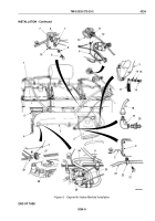
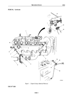
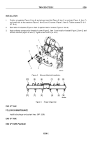
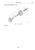
Position six gaskets (Figure 2, Item 9) and exhaust manifold (Figure 2, Item 2) on three cylinder head dowels
(Figure 2, Item 10) for installation.
2.
Install four clamps (Figure 2, Item 8), eight key washers (Figure 2, Item 7), screws (Figure 2, Item 6), and oil
dipstick bracket (Figure 2, Item 14) on exhaust manifold (Figure 2, Item 2).
3.
Reposition oil dipstick bracket (Figure 2, Item 14) for installation.
4.
Connect heater inlet hose (Figure 2, Item 13) to shutoff valve (Figure 2, Item 11) on water manifold
(Figure
2,
Item 1) and tighten clamp (Figure 2, Item 12).
5.
Tighten screw (Figure 2, Item 17) and nut (Figure 2, Item 15) on dipstick tube (Figure 2, Item 16).
6.
Install gasket (Figure 2, Item 3) between exhaust manifold (Figure 2, Item 2) and front exhaust pipe
(Figure
2, Item 5).
7.
Position manifold coupling clamp (Figure 2, Item 4) on front exhaust pipe (Figure 2, Item 5).
TM 9-2320-272-23-2
0235
0235-4
Back to Top

