TM-9-2320-272-23-2 - Page 659 of 1417
ACCESSORY DRIVE DISASSEMBLY
1.
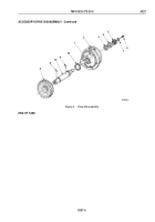
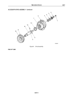
Using dial indicator gauge, measure end play of driveshaft (Figure 3, Item 10). Note end play measurement
for reference.
2.
Remove screw (Figure 3, Item 6) and washer (Figure 3, Item 7) from driveshaft (Figure 3, Item 10).
3.
Using arbor press and mandrel, press driveshaft (Figure 3, Item 10) through coupling halfshaft
(Figure
3,
Item
5).
4.
Remove driveshaft (Figure 3, Item 10), drive gear (Figure 3, Item 8), thrust washers
(Figure
3,
Items
3
and
12), and washer (Figure 3, Item 4) from accessory drive housing (Figure 3, Item 2)
and slide through bushing (Figure
3, Item 1) in accessory drive housing.
5.
Using arbor press and mandrel, press driveshaft (Figure 3, Item 10) through drive gear (Figure 3, Item 8).
NOTE
Do not remove dowel pins unless damaged.
6.
Remove cotter pins (Figure 3, Items 9 and 11) from driveshaft (Figure 3, Item 10).
TM 9-2320-272-23-2
0237
0237-4
Back to Top

