TM-9-2320-272-23-2 - Page 663 of 1417
ACCESSORY DRIVE ASSEMBLY
1.
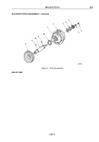
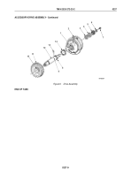
Install cotter pin (Figure 5, Item 13) in hole (Figure 5, Item 9) of driveshaft (Figure 5, Item 12).
NOTE
Remaining dowel pin is installed with accessory drive pulley.
2.
Align slot (Figure 5, Item 10) in bore of drive gear (Figure 5, Item 11) with cotter pin (Figure 5, Item 13) and
press drive gear on driveshaft (Figure 5, Item 12) over cotter pin. Ensure drive gear is seated on shoulder
(Figure 5, Item 8).
3.
Install large thrust washer (Figure 5, Item 14) on front of accessory drive housing (Figure 5, Item 2).
4.
Install driveshaft (Figure 5, Item 12) and drive gear (Figure 5, Item 11) through thrust washer
(Figure
5,
Item
14) and bushing (Figure 5, Item 1) in accessory drive housing (Figure 5, Item 2).
5.
Install thrust washer (Figure 5, Item 3) over driveshaft (Figure 5, Item 12) and position in accessory drive
housing (Figure 5, Item 2). Ensure grooved side of thrust washer faces away from accessory drive housing.
6.
Install washer (Figure 5, Item 4) on driveshaft (Figure 5, Item 12) against thrust washer (Figure 5, Item 3).
NOTE
Ensure flat end of coupling halfshaft faces away from accessory drive housing.
7.
Press coupling halfshaft (Figure 5, Item 5) on driveshaft (Figure 5, Item 12) until flush with end.
8.
Measure driveshaft (Figure 5, Item 12) end play. End play should be 0.002 to 0.012 in. (0.05 to 0.26 mm). If
end play is not within limits, press driveshaft through coupling halfshaft (Figure 5, Item 5) to obtain proper end
play.
9.
Install washer (Figure 5, Item 6) and screw (Figure 5, Item 7) on driveshaft (Figure 5, Item 12). Tighten screw
30 to 35 lb-ft (41 to 47 N·m).
TM 9-2320-272-23-2
0237
0237-8
Back to Top

