TM-9-2320-272-23-2 - Page 667 of 1417
ACCESSORY DRIVE INSTALLATION - Continued
4.
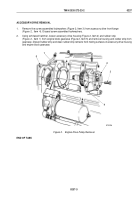
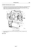
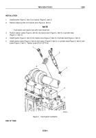
Install accessory drive housing (Figure 8, Item 2) and rubber strip (Figure 8, Item 1) on engine block gearcase
(Figure 8, Item 5) with five screw assembled lockwashers (Figure 8, Item 3). Ensure timing marks
(Figure
6,
Item
2) on accessory drive gear (Figure 6, Item 3) and camshaft gear (Figure 6, Item 6) align.
Tighten screw assembled lockwashers 40 to 45 lb-ft (54 to 61 N·m).
2
1
5
4
3
M7101DAA
Figure 8.
Drive Installation.
5.
Wrap pipe plug (Figure 6, Item 4) threads with antiseize tape and install in front gearcase cover
(Figure
6,
Item 1).
END OF TASK
TM 9-2320-272-23-2
0237
0237-12
Back to Top


