TM-9-2320-272-23-2 - Page 661 of 1417
ACCESSORY DRIVE CLEANING AND INSPECTION
WARNING
•
Solvent cleaning compound is flammable and toxic. Do not use near an open flame and
always have a fire extinguisher nearby when solvents are used. Use only in well-
ventilated places, wear protective clothing, and dispose of cleaning rags in approved
container. Failure to comply may result in damage to equipment, injury, or death to
personnel.
•
Eyeshields must be worn when cleaning with compressed air. Compressed air source
will not exceed 30 psi (207 kPa). Failure to comply may result in injury or death to
personnel.
1.
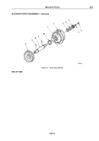
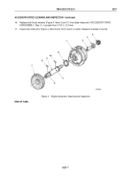
Clean accessory drive housing (Figure 4, Item 1) with solvent cleaning compound and blow out passages and
bore with compressed air.
2.
Inspect accessory drive housing (Figure 4, Item 1) for breaks and cracks. Replace if broken or cracked.
3.
Inspect bushing (Figure 4, Item 2) on accessory drive housing (Figure 4, Item 1) for pitting, galling, and cracks.
Replace bushing if pitted, galled, or cracked.
4.
Check inside diameter of bushing (Figure 4, Item 2) at both ends. Replace bushing if either measurement is
greater than 1.321 in. (33.6 mm).
NOTE
Perform Steps (5) and (6) only if bushing must be replaced.
5.
Using arbor press and mandrel, press bushing (Figure 4, Item 2) from accessory drive housing
(Figure
4,
Item
1).
6.
Using arbor press and mandrel, install bushing (Figure 4, Item 2) in accessory drive housing
(Figure
4,
Item
1) flush with face.
7.
Clean driveshaft (Figure 4, Item 9) with solvent cleaning compound.
8.
Inspect driveshaft (Figure 4, Item 9) for breaks, cracks, and galling. Replace if broken, cracked, or galled.
9.
Inspect driveshaft (Figure 4, Item 9) for stripped or crossed threads. Repair or replace driveshaft
(Figure
4,
Item 9) if threads are stripped or crossed.
10.
Check driveshaft (Figure 4, Item 9) outside diameter at bushing (Figure 4, Item 2) location. Replace driveshaft
if outside diameter is less than 1.310 in. (33.27 mm).
11.
Inspect dowel pin holes (Figure 4, Items 5 and 6) of driveshaft (Figure 4, Item 9). Discard driveshaft if holes
are enlarged.
12.
Using solvent cleaning compound, clean drive gear (Figure 4, Item 7) and coupling halfshaft
(Figure
4,
Item
4).
13.
Inspect drive gear (Figure 4, Item 7) and coupling halfshaft (Figure 4, Item 4) for breaks, cracks, and galling
in bore. Replace if cracked, broken, or bore shows galling.
14.
Inspect drive gear (Figure 4, Item 7) and coupling halfshaft (Figure 4, Item 4) for chipped and broken teeth.
Replace drive gear and coupling halfshaft if teeth are broken or chipped.
15.
Inspect thrust washers (Figure 4, Items 3 and 11) for cracks and scoring. Replace if cracked, broken, or scored.
TM 9-2320-272-23-2
0237
0237-6
Back to Top

