TM-9-2320-272-23-2 - Page 655 of 1417
INSTALLATION
1.
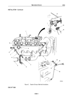
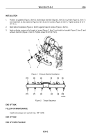
Position six gaskets (Figure 2, Item 6) and exhaust manifold (Figure 2, Item 3) on cylinder (Figure
2,
Item
7)
and install with six key washers (Figure 2, Item 5) and 12 screws (Figure 2, Item 4). Tighten screws 30
lb-ft
(41
N·m).
2.
Bend tabs of lockplates (Figure 2, Item 5) against head of screws (Figure 2, Item 4).
3.
Apply antiseize compound to threads of screw (Figure 2, Item 1) and install on bracket (Figure 2, Item 2) and
exhaust manifold (Figure 2, Item 3). Tighten screw 30 lb-ft (41 N·m).
M9808DAA
7
6
4
3
5
1
2
Figure 2.
Exhaust Manifold Installation.
M9385DAA
[12]
[11]
[7]
[3]
[2]
[6]
[10]
[8]
[4]
[1]
[5]
[9]
Figure 3.
Torque Sequence.
END OF TASK
FOLLOW-ON MAINTENANCE
Install turbocharger and coolant lines. (WP
0249)
END OF TASK
END OF WORK PACKAGE
TM 9-2320-272-23-2
0236
0236-2
Back to Top


