TM-9-2320-272-23-2 - Page 643 of 1417
CLEANING AND INSPECTION
1.
Brush and clean intake manifold and air intake connector and inspect for breaks, cracks, and elongated holes.
Replace if broken, cracked, or if holes are elongated (WP
0214).
WARNING
Eyeshields must be worn when cleaning with compressed air. Compressed air source will
not exceed 30 psi (207 kPa). Failure to comply may result in injury or death to personnel.
2.
Clean internal passages of intake manifold and air intake connector with compressed air and inspect threaded
holes, screws, pipe plugs, and adapter for stripped or crossed threads. Repair or replace if threaded parts have
stripped or crossed threads (WP
0214).
END OF TASK
ASSEMBLY
NOTE
Male pipe threads must be wrapped with antiseize tape before installation.
1.
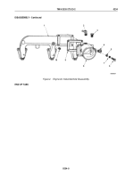
Install adapter (Figure 3, Item 4) and plug (Figure 3, Item 3) in air intake connector (Figure 3, Item 8).
2.
Install pipe plug (Figure 3, Item 10) in intake manifold (Figure 3, Item 1).
NOTE
Perform Step (3) for late model engines.
3.
Install elbow (Figure 3, Item 2) on air intake connector (Figure 3, Item 8).
4.
Install air intake connector (Figure 3, Item 8) and gasket (Figure 3, Item 9) on intake manifold
(Figure
3,
Item
1) with two screws (Figure 3, Item 6), lockwashers (Figure 3, Item 7), and washers
(Figure
3,
Item
5). Tighten screws 25 to 30 lb-ft (34 to 41 N·m).
TM 9-2320-272-23-2
0234
0234-6
Back to Top


