TM-9-2320-272-23-2 - Page 635 of 1417
ASSEMBLY
1.
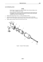
Align index marks on oil cooler element (Figure 4, Item 4) and install in cooler housing (Figure 4, Item 6).
NOTE
Apply engine oil to lubricate o-rings before installation.
2.
Install two o-rings (Figure 4, Item 7) and retaining rings (Figure 4, Item 8) in each end of cooler housing
(Figure
4,
Item
6).
3.
Wrap end of elbow (Figure 4, Item 1) with antiseize tape and install in end cover (Figure 4, Item 10).
4.
Wrap pipe plug (Figure 4, Item 5) with sealing tape and install in cooler housing (Figure 4, Item 6).
5.
Install gasket (Figure 4, Item 9) and end cover (Figure 4, Item 10) on cooler housing (Figure 4, Item 6) with
four lockwashers (Figure 4, Item 3) and screws (Figure 4, Item 2). Tighten screws 30 to 35 lb-ft
(41
to
47
N·m).
8
7
6
5
7
8
9
10
1
3
2
4
M9611DAA
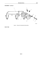
Figure 4.
Engine Oil Cooler Assembly.
END OF TASK
INSTALLATION
1.
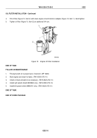
Install gasket (Figure 5, Item 5) and oil cooler (Figure 5, Item 8) on engine block (Figure 5, Item 4) with five
lockwashers (Figure 5, Item 6) and screws (Figure 5, Item 7). Tighten screws 30 to 35 lb-ft (40 to 47 N·m).
2.
Connect bushing (Figure 5, Item 2) and air compressor coolant line (Figure 5, Item 3) to oil cooler elbow
(Figure
5,
Item
1).
TM 9-2320-272-23-2
0233
0233-6
Back to Top

