TM-9-2320-272-23-2 - Page 636 of 1417
INSTALLATION - Continued
3.
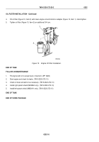
Install adapter (Figure 5, Item 13) and shutoff valve (Figure 5, Item 16) on oil cooler (Figure 5, Item 8).
4.
Connect surge tank-to-oil cooler hose (Figure 5, Item 12) to oil cooler (Figure 5, Item 8) with clamp
(Figure
5,
Item
11).
5.
Connect transmission cooler-to-oil hose (Figure 5, Item 9) to oil cooler (Figure 5, Item 8) with hose clamp
(Figure 5, Item 10).
6.
Connect heater hose (Figure 5, Item 14) to shutoff valve (Figure 5, Item 16) with hose clamp
(Figure
5,
Item
15).
1
2
4
5
3
6
7
8
9
10
11
12
14
13
15
16
M9612DAA
Figure 5.
Engine Oil Cooler Installation.
END OF TASK
TM 9-2320-272-23-2
0233
0233-7
Back to Top


