TM-9-2320-272-23-2 - Page 889 of 1417
INSTALLATION
1.
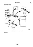
Install spring (Figure 2, Item 11) and clevis rod (Figure 2, Item 8) on accelerator rod (Figure 2, Item 1) and
secure with spring pin (Figure 2, Item 10).
2.
Install ball joint (Figure 2, Item 4) on accelerator rod (Figure 2, Item 1).
3.
Position accelerator rod (Figure 2, Item 1) and ball joint (Figure 2, Item 4) on link assembly
(Figure
2,
Item
6).
4.
While holding nut (Figure 2, Item 5), install and tighten locknut (Figure 2, Item 7) on ball joint
(Figure
2,
Item
4).
NOTE
If holes in clevis and throttle lever do not align, go to adjustment.
5.
Connect clevis rod (Figure 2, Item 8) to throttle lever (Figure 2, Item 13) with screw (Figure 2, Item 12) and
locknut (Figure 2, Item 9).
6.
Connect return spring (Figure 2, Item 2) to accelerator rod (Figure 2, Item 1) and link assembly
(Figure
2,
Item
6).
TM 9-2320-272-23-2
0268
0268-4
Back to Top


