TM-9-2320-272-23-2 - Page 895 of 1417
REMOVAL
1.
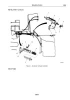
Compress spring-loaded sleeve (Figure 1, Item 22) and remove quick-disconnect socket (Figure 1, Item 21)
from ball joint (Figure 1, Item 1) on control lever (Figure 1, Item 2).
2.
Remove throttle return spring (Figure 1, Item 14) from accelerator rod (Figure 1, Item 15) and throttle shaft
(Figure 1, Item 6).
3.
Remove locknut (Figure 1, Item 9) and ball joint (Figure 1, Item 12) from bracket (Figure 1, Item 8).
Discard
locknut.
4.
Loosen screw (Figure 1, Item 11) and remove connector (Figure 1, Item 10) and cable (Figure 1, Item 3) from
bracket (Figure 1, Item 8).
5.
Remove two cotter pins (Figure 1, Item 5), washers (Figure 1, Item 7), throttle shaft (Figure 1, Item 6), and
bracket (Figure 1, Item 8) from bracket (Figure 1, Item 4). Discard cotter pins.
TM 9-2320-272-23-2
0269
0269-2
Back to Top


