TM-9-2320-272-23-2 - Page 891 of 1417
ADJUSTMENT
NOTE
Perform Step (1) only if link assembly was removed.
1.
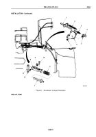
Disconnect return spring (Figure 3, Item 2) from link assembly (Figure 3, Item 6) and accelerator rod
(Figure
3,
Item
1).
2.
Remove screw (Figure 3, Item 12) and locknut (Figure 3, Item 9). Discard locknut and screw.
NOTE
Assistant will help with Steps (3) through (8).
3.
Push throttle lever (Figure 3, Item 13) forward to FULL THROTTLE position.
4.
Pull clevis rod (Figure 3, Item 8) forward as far as possible.
5.
Loosen jamnut (Figure 3, Item 3) and hand-turn accelerator rod (Figure 3, Item 1) to shorten or lengthen as
needed to align holes in clevis rod (Figure 3, Item 8) and throttle lever (Figure 3, Item 13).
6.
Install clevis (Figure 3, Item 8) on throttle lever (Figure 3, Item 13) with screw (Figure 3, Item 12) and locknut
(Figure 3, Item 9).
7.
Tighten jamnut (Figure 3, Item 3) against ball joint (Figure 3, Item 4).
8.
Connect return spring (Figure 3, Item 2) to accelerator rod (Figure 3, Item 1) and link assembly
(Figure
3,
Item
6).
TM 9-2320-272-23-2
0268
0268-6
Back to Top


