TM-9-2320-272-23-3 - Page 1212 of 1469
ASSEMBLY
1.
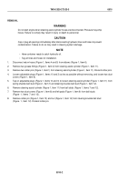
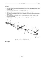
Install clamp (Figure 3, Item 6) loosely on socket assembly (Figure 3, Item 5) with screw (Figure 3, Item 7) and
nut (Figure 3, Item 11).
2.
Install socket assembly (Figure 3, Item 5) on shaft (Figure 3, Item 10).
3.
Tighten nut (Figure 3, Item 11) on clamp (Figure 3, Item 6) 30 to 40 lb-ft (41 to 54 N·m).
4.
Install ring (Figure 3, Item 4), spring (Figure 3, Item 3), and two seat valves (Figure 3, Item 2) in socket assembly
(Figure 3, Item 5).
5.
Install adjustable plugs (Figure 3, Item 1) loosely on steering assist cylinder (Figure 3, Item 8) and socket
assembly (Figure 3, Item 5).
6.
Install two adapter elbows (Figure 3, Item 9) on steering assist cylinder (Figure 3, Item 8).
1
M5039DAA
1
2
3
4
5
6
8
7
9
11
10
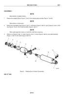
Figure 3.
Steering Assist Cylinder Assembly.
END OF TASK
TM 9-2320-272-23-3
0510
0510-5
Back to Top


