TM-9-2320-272-23-3 - Page 1355 of 1469
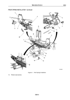
FRONT SPRING INSTALLATION
1.
Raise one end of spring (Figure 6, Item 1) over tie rod (Figure 6, Item 13) and axle (Figure 6, Item 17).
2.
Edge spring (Figure 6, Item 1) forward until spring center bolt (Figure 6, Item 22) enters hole in center of lower
spring seat (Figure 6, Item 12).
3.
Position upper spring seat (Figure 6, Item 21) over top of spring (Figure 6, Item 1).
4.
Place two U-bolts (Figure 6, Item 11) over upper spring seat (Figure 6, Item 23) and through holes in lower
spring seat (Figure 6, Item 12), with long end toward wheel.
5.
Install two U-bolts (Figure 6, Item 11) on shock absorber mounting plate (Figure 6, Item 14) with four
lockwashers (Figure 6, Item 15) and nuts (Figure 6, Item 16). Tighten nuts to 350 to 400 lb-ft
(475
to
542
N·m).
6.
Raise spring (Figure 6, Item 1) to frame (Figure 6, Item 20) until spring eyes (Figure 6, Item 8) and
(Figure
6,
Item
3) align with holes in hanger (Figure 6, Item 1) and shackle (Figure 6, Item 6).
7.
Install pin (Figure 6, Item 4) through front spring eye (Figure 6, Item 3) and hanger (Figure 6, Item 1) with screw
(Figure 6, Item 2) and locknut (Figure 6, Item 5). Groove in pin must be in position to angle of screw holes
before screw can be installed.
8.
Install pin (Figure 6, Item 10) through spring eye (Figure 6, Item 8) and shackle (Figure 6, Item 6) with screw
(Figure 6, Item 7) and locknut (Figure 6, Item 9). Groove in pin must be in position to angle of screw holes
before screw can be installed.
NOTE
All male pipe threads must be wrapped with antiseize tape prior to installation.
9.
Connect two air lines (Figure 6, Item 19) to service brake chamber (Figure 6, Item 18).
TM 9-2320-272-23-3
0534
0534-8
Back to Top


