TM-9-2320-272-23-3 - Page 1362 of 1469
INSTALLATION
1.
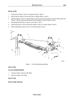
Install hanger (Figure 2, Item 2) on spring (Figure 2, Item 12) with bolts (Figure 2, Item 18) and locknuts
(Figure 2, Item 16). Torque locknuts to 150 to 170 lb-ft (203.4 to 230.5 N·m).
2.
Install bushing (Figure 2, Item 5) in shackle (Figure 2, Item 4).
3.
Loosely thread screw (Figure 2, Item 7) on shackle (Figure 2, Item 4).
4.
Install shackle (Figure 2, Item 4) on hanger (Figure 2, Item 2).
5.
Install shackle pin (Figure 2, Item 14) in shackle (Figure 2, Item 4) and hanger (Figure 2, Item 2). Ensure pin
slot (Figure 2, Item 13) is positioned downward to allow installation of screw (Figure 2, Item 3).
6.
Install grease fitting (Figure 2, Item 15) in shackle pin (Figure 2, Item 14).
7.
Install screw (Figure 2, Item 3) and locknut (Figure 2, Item 1) on shackle (Figure 2, Item 4) and hanger
(Figure
2,
Item
2).
8.
Lower vehicle until spring eye (Figure 2, Item 11) aligns with holes in shackle (Figure 2, Item 4).
9.
Install shackle pin (Figure 2, Item 9) in shackle (Figure 2, Item 4) and spring eye (Figure 2, Item 11). Ensure
pin slot (Figure 2, Item 8) is positioned downward to allow installation of screw (Figure 2, Item 7).
10.
Install grease fitting (Figure 2, Item 10) on shackle pin (Figure 2, Item 9) and hanger (Figure 2, Item 2).
11.
Tighten screw (Figure 2, Item 7) and install locknut (Figure 2, Item 6) on shackle (Figure 2, Item 4).
12.
Remove jack stands from under frame (Figure 2, Item 17).
10
M9178DAA
9
8
7
6
11
12
13
14
15
1
2
3
4
5
16
2
16
17
18
Figure 2.
Front Spring Shackle and Shackle Hanger Installation.
END OF TASK
TM 9-2320-272-23-3
0535
0535-3
Back to Top


