TM-9-2320-272-23-3 - Page 1351 of 1469
FRONT SPRING REMOVAL - Continued
CAUTION
Cap or plug all openings immediately after disconnecting lines or hoses to prevent
contamination. Failure to do so may result in brake system damage.
6.
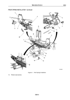
Disconnect two air lines (Figure 2, Item 7) from service brake chamber (Figure 2, Item 6).
7.
Place jack stands under frame (Figure 2, Item 9) at rear of hanger (Figure 2, Item 2).
NOTE
Support axle when removing U-bolts.
8.
Remove four nuts (Figure 2, Item 5), lockwashers (Figure 2, Item 4), and shock absorber mounting plate
(Figure
2,
Item
3) from two U-bolts (Figure 2, Item 1). Discard lockwashers.
NOTE
•
Frame may have to be raised further to provide clearance for U-bolts removal.
•
If U-bolts must be forced, place a piece of wood between hammer and bolt to
prevent
damage.
9.
Remove two U-bolts (Figure 2, Item 1) and upper spring seat (Figure 2, Item 10) from springs
(Figure
2,
Item
8).
M10313DAA
6
5
4
3
7
8
9
10
2
1
Figure 2.
Steering Cylinder Removal.
TM 9-2320-272-23-3
0534
0534-4
Back to Top


