TM-9-2320-272-23-3 - Page 1417 of 1469
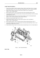
LOWER TORQUE ROD INSTALLATION
CAUTION
Ensure 6 in. (15.24 cm) clearance remains between top of upper spring bracket and bottom
of frame rail for all vehicles except M936/A1/A2 model vehicles. For the M936/A1/A2 model
vehicles, this clearance is 7-1/4 in. (18.4 cm). If clearance is not correct, torque rods will
be
damaged.
1.
Install lower torque rod (Figure 7, Item 7) ball shaft (Figure 7, Item 11) to lower torque rod bracket
(Figure
7,
Item
8) with slotted nut (Figure 7, Item 12).
2.
Install torque rod ball shaft (Figure 7, Item 6) on spring seat bracket (Figure 7, Item 3) with slotted nut
(Figure
7,
Item
4).
3.
Tighten slotted nuts (Figure 7, Items 4 and 12) 350 to 400 lb-ft (475 to 542 N·m), and install cotter pins
(Figure
7,
Items 5 and 13).
4.
Install lower torque rod bracket (Figure 7, Item 8) and upper spring bracket (Figure 7, Item 14) on rear axle
(Figure 7, Item 2) with four screws (Figure 7, Item 1), lockwashers (Figure 7, Item 9), and nuts
(Figure
7,
Item
10). Tighten nuts 280 to 360 lb-ft (380 to 488 N·m). For M936/A1/A2 model vehicles tighten
nuts 320 to 425 lb-ft (434 to 576 N·m).
M9198DAA
3
4
5
6
7
11
12
13
10
9
8
1
2
14
Figure 7.
Lower Torque Rod Installation.
END OF TASK
TM 9-2320-272-23-3
0544
0544-10
Back to Top


