TM-9-2320-272-23-3 - Page 315 of 1469
INSTALLATION - Continued
NOTE
•
Use engine barring tool to rotate engine crankshaft when aligning flywheel to converter
screw holes.
•
The use of shim stock tube in torque converter access hole prevents converter screw
from falling down behind flywheel. A loose screw may cause a lockup condition,
preventing crankshaft rotation required to install remaining screws.
11.
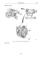
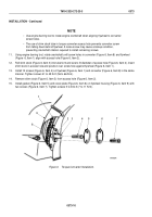
Using engine barring tool, rotate crankshaft until screw holes in converter (Figure 6, Item 8) and flywheel
(Figure
6, Item 1) align with access hole (Figure 6, Item 2).
12.
Roll shim stock (Figure 6, Item 3) into tube form and size to fit diameter of access hole (Figure 6, Item 2). Insert
shim stock in access hole and position over screw hole against flywheel (Figure 6, Item 1).
13.
Install 12 screws (Figure 6, Item 4) on flywheel (Figure 6, Item 1) and converter (Figure 6, Item 8) in the same
manner. Tighten screws 41 to 49 lb-ft (56 to 66 N·m).
14.
Remove shim stock (Figure 6, Item 3) from access hole (Figure 6, Item 2).
15.
Install gasket (Figure 6, Item 5) and cover plate (Figure 6, Item 6) on flywheel housing (Figure 6, Item 9) with
two screws (Figure 6, Item 7). Tighten screws 5 to 8 lb-ft (7 to 11 N·m).
M7008DAA
8
7
6
5
3
9
2
1
4
Figure 6.
Torque Converter Installation.
TM 9-2320-272-23-3
0373
0373-10
Back to Top


