TM-9-2320-272-23-3 - Page 407 of 1469
REMOVAL
NOTE
Ensure transfer case shift lever is in HIGH position to prevent propeller shaft from turning
when loosening screws.
1.
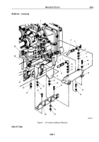
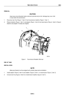
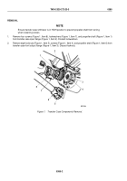
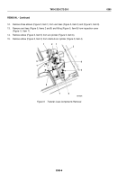
Remove four screws (Figure 1, Item 8), lockwashers (Figure 1, Item 7), and propeller shaft (Figure 1, Item 1)
from transfer case input flange (Figure 1, Item 2). Discard lockwashers.
2.
Remove eight locknuts (Figure 1, Item 5), screws (Figure 1, Item 4), and propeller shaft (Figure 1, Item 6) from
transfer case front output flange (Figure 1, Item 3). Discard locknuts.
M9761DAA
3
4
5
6
7
8
2
1
Figure 1.
Transfer Case Components Removal.
TM 9-2320-272-23-3
0385
0385-2
Back to Top

