TM-9-2320-272-23-3 - Page 705 of 1469
INSTALLATION
CAUTION
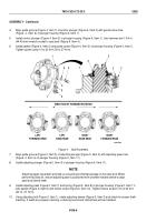
Failure to tighten nuts in proper sequence can crack brake spider.
1.
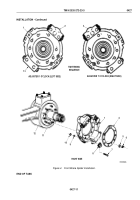
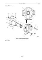
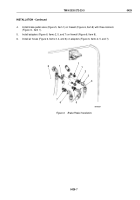
Install two clips (Figure 6, Item 5) on brake spider (Figure 6, Item 1) with screws (Figure 6, Item 4), lockwashers
(Figure 6, Item 6), and nuts (Figure 6, Item 7).
2.
Apply adhesive on rear axle housing (Figure 6, Item 8) and brake spider (Figure 6, Item 1) mating surfaces.
NOTE
Assistant will help with Step (3).
3.
Position threaded holes 3 and 4 of brake spider (Figure 6, Item 1) on axle housing mating surface at 3 and
9
o'clock positions, and install two washers (Figure 6, Item 13) and screws (Figure 6, Item 12) through back
of flange (Figure 6, Item 9) into threaded holes 3 and 4 of brake spider (Figure 6, Item 1).
4.
Install eight washers (Figure 6, Item 2), screws (Figure 6, Item 3), washers (Figure 6, Item 11), and nuts
(Figure
6,
Item
10) through brake spider (Figure 6, Item 1) and flange (Figure 6, Item 9). Tighten nuts
110
to
145
lb-ft (149 to 196 N·m) in sequence shown.
TM 9-2320-272-23-3
0428
0428-8
Back to Top

