TM-9-2320-272-23-3 - Page 700 of 1469
DISASSEMBLY - Continued
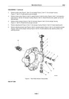
2.
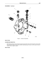
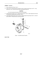
Remove guide screw (Figure 2, Item 10) and gasket (Figure 2, Item 11) from plunger housing
(Figure
2,
Item
5). Discard guide screw and gasket.
3.
Remove hollow screw (Figure 2, Item 9), gasket (Figure 2, Item 8), spring (Figure 2, Item 7), and adjusting
pawl (Figure 2, Item 6) from plunger housing (Figure 2, Item 5). Discard hollow screw, gasket, spring, and
adjusting pawl.
4.
Remove anchor plunger (Figure 2, Item 12) and seal (Figure 2, Item 13) from plunger housing
(Figure
2,
Item
5). Discard anchor plunger and seal.
5.
Remove adjusting bolt (Figure 2, Item 1) from plunger housing (Figure 2, Item 5). Discard adjusting bolt.
6.
Remove adjusting plunger seal (Figure 2, Item 2), adjusting sleeve (Figure 2, Item 3), and adjusting plunger
(Figure 2, Item 4) from plunger housing (Figure 2, Item 5). Discard adjusting seal, adjusting sleeve, and
adjusting plunger.
2
1
14
3
4
5
6
7
8
9
10
11
12
13
M6195DAA
Figure 2.
Rear Brake Actuator Disassembly.
END OF TASK
TM 9-2320-272-23-3
0428
0428-3
Back to Top

