TM-9-2320-272-23-3 - Page 703 of 1469
ASSEMBLY - Continued
4.
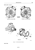
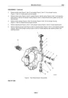
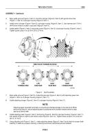
Align guide groove (Figure 4, Item 7) of anchor plunger (Figure 4, Item 5) with guide screw hole
(Figure
4,
Item
6) of plunger housing (Figure 4, Item 1).
5.
Install anchor plunger (Figure 4, Item 5) in plunger housing (Figure 4, Item 1). Use hammer and 1-3/4 in.
(44.45 mm) wrench socket to seat seal (Figure 4, Item 4).
6.
Install gasket (Figure 4, Item 2) and guide screw (Figure 4, Item 3) on plunger housing (Figure 4, Item 1).
Tighten guide screw 15 to 20 lb-ft (20 to 27 N·m).
LEFT
FORWARD REAR
LEFT
REAR REAR
RIGHT
REAR REAR
RIGHT
FORWARD REAR
DIRECTION OF FORWARD ROTATION
7
4
5
6
3
2
1
1
4
5
2
3
M10374DAA
Figure 4.
Seal Assembly.
7.
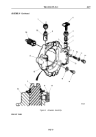
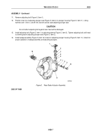
Align guide groove (Figure 5, Item 5) of adjusting plunger (Figure 5, Item 4) with adjusting pawl hole
(Figure
5, Item
6) of plunger housing (Figure 5, Item 11).
8.
Install adjusting plunger (Figure 5, Item 4) in plunger housing (Figure 5, Item 11).
NOTE
Adjusting pawls have teeth and flats on one end and chamfered edge on the other end. When
performing Step (9), ensure adjusting pawl is positioned with chamber toward sleeve to align
pawl and sleeve teeth.
9.
Install adjusting pawl (Figure 5, Item 7) and spring (Figure 5, Item 8) in plunger housing (Figure 5, Item 11)
with gasket (Figure 5, Item 9) and hollow screw (Figure 5, Item 10). Tighten hollow screw to 15 to 20 lb-ft
(20
to
27
N·m).
10.
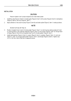
Using adjusting bolt (Figure 5, Item 1), rotate adjusting sleeve (Figure 5, Item 3) and check for proper teeth
meshing. If teeth are properly meshing, a clicking sound and ratchet feel will be indicated.
TM 9-2320-272-23-3
0428
0428-6
Back to Top

