TM-9-2320-272-23-3 - Page 704 of 1469
ASSEMBLY - Continued
11.
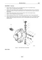
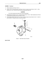
Remove adjusting bolt (Figure 5, Item 1).
12.
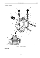
Position inner lip of adjusting plunger seal (Figure 5, Item 2) in plunger housing (Figure 5, Item 11). Using
hammer and 1-3/4 in. (44.45 mm) wrench socket, seat adjusting plunger seal.
CAUTION
Do not bottom adjusting bolt against seal. Seal will be damaged.
13.
Install adjusting bolt (Figure 5, Item 1) in adjusting sleeve (Figure 5, Item 3). Tighten adjusting bolt until head
is showing above adjusting plunger seal (Figure 5, Item 2).
14.
Install wedge assembly (Figure 5, Item 12) in back of adjusting plunger housing (Figure 5, Item 11). Check for
proper operation of wedge assembly and adjusting plungers.
2
1
12
3
4
5
6
7
8
9
10
11
M6197DAA
Figure 5.
Rear Brake Actuator Assembly.
END OF TASK
TM 9-2320-272-23-3
0428
0428-7
Back to Top

