TM-9-2320-272-23-3 - Page 695 of 1469
INSTALLATION
1.
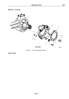
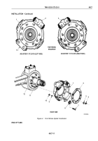
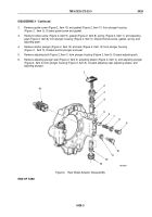
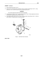
Install two clips (Figure 4, Item 8) on brake spider (Figure 4, Item 1) with two screws (Figure 4, Item 7),
lockwashers (Figure 4, Item 9), and nuts (Figure 4, Item 10).
2.
Apply gasket sealant to spindle (Figure 4, Item 11) and brake spider (Figure 4, Item 1) mating surfaces.
CAUTION
Failure to tighten nuts in proper sequence can crack brake spider.
NOTE
Tighten front brake spider after installing front wheel dust covers.
3.
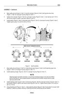
Install brake spider (Figure 4, Item 1) and brake spider slinger (Figure 4, Item 4) on studs (Figure 4, Item 12)
with adjustable anchor plunger (Figure 4, Item 2) at 1 o'clock position (left side) and adjustable anchor plunger
(Figure 4, Item 3) at 11 o'clock position (right side) with nine washers (Figure 4, Item 5) and nuts
(Figure
4,
Item
6). Tighten nuts to 110 to 145 lb-ft (149 to 196 N·m) in sequence shown.
TM 9-2320-272-23-3
0427
0427-10
Back to Top

