TM-9-2320-272-23-3 - Page 71 of 1469
INSTALLATION
1.
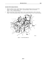
Route cables (Figure 2, Items 3 and 9) through insulating hose (Figure 2, Item 7) and battery box
(Figure
2,
Item 8).
2.
Pull cables (Figure 2, Items 3 and 9) through insulating hose (Figure 2, Item 7) until exposed outside cab
(Figure 2, Item 6).
3.
Install gasket (Figure 2, Item 4) and insulator (Figure 2, Item 5) on slave receptacle (Figure 2, Item 14).
4.
Install battery cables (Figure 2, Items 3 and 9) on slave receptacle (Figure 2, Item 14) with two lockwashers
(Figure 2, Item 2) and screws (Figure 2, Item 1).
5.
Insert slave receptacle (Figure 2, Item 14) in cab (Figure 2, Item 6) and position insulating hose
(Figure
2,
Item
7) over screws (Figure 2, Item 1). Install slave receptacle with three screws
(Figure
2,
Item
12) and nuts (Figure 2, Item 10).
6.
Install cover (Figure 2, Item 13) and rope (Figure 2, Item 11) on slave receptacle (Figure 2, Item 14) with screw
(Figure 2, Item 12) and nut (Figure 2, Item 10).
TM 9-2320-272-23-3
0353
0353-4
Back to Top


