TM-9-2320-272-23-3 - Page 65 of 1469
PLUG ASSEMBLY
NOTE
Refer to TB SIG-222 for soldering instructions.
1.
Strip cable insulation (Figure 4, Item 6) to equal depth of solder wells (Figure 4, Item 1) of inserts
(Figure
4,
Item
2).
2.
Pass cable ends (Figure 4, Item 8) through grommet retaining nut (Figure 4, Item 7), grommet
(Figure
4,
Item
3), and coupling nut (Figure 4, Item 5).
3.
Insert ends (Figure 4, Item 8) into solder wells (Figure 4, Item 1) of inserts (Figure 4, Item 2) and solder.
4.
Slide grommet (Figure 4, Item 3) over inserts (Figure 4, Item 2) and press into shell assembly
(Figure
4,
Item
4) until seated.
5.
Slide grommet retaining nut (Figure 4, Item 7) up cable (Figure 4, Item 8) and install on shell assembly
(Figure
4,
Item
4).
6
7
8
1
2
3
4
5
MALE INSERT
OR
FEMALE INSERT
M8050DAA
1
2
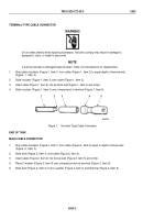
Figure 4.
Plug Assembly.
END OF TASK
TM 9-2320-272-23-3
0352
0352-4
Back to Top


