TM-9-2320-272-23-3 - Page 865 of 1469
REMOVAL
1.
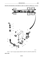
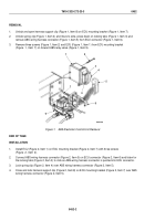
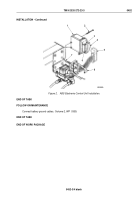
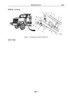
Unlock and open harness support clip (Figure 1, Item 8) on ECU mounting bracket (Figure 1, Item 7).
2.
Unlock spring clip (Figure 1, Item 4) and move to side, press down on locking tabs (Figure 1, Item 3) and
remove ABS wiring harness connector (Figure 1, Item 5) from ECU connector (Figure 1, Item 6).
3.
Remove three screws (Figure 1, Item 2) and ECU (Figure 1, Item 1) from ECU mounting bracket
(Figure
1,
Item
7) on forward ABS relay valve (Figure 1, Item 9).
1
2
3
M9421DAA
4
5
8
9
6
7
Figure 1.
ABS Electronic Control Unit Removal.
END OF TASK
INSTALLATION
1.
Install ECU (Figure 2, Item 1) on ECU mounting bracket (Figure 2, Item 7) with three screws
(Figure
2,
Item
2).
2.
Connect ABS wiring harness connector (Figure 2, Item 5) on ECU connector (Figure 2, Item 6) and listen for
the locking tabs (Figure 2, Item 3) to click as ABS wiring harness connector is pushed into ECU connector.
3.
Lock spring clip (Figure 2, Item 4) over ABS wiring harness connector (Figure 2, Item 5).
4.
Close and lock harness support clip (Figure 2, Item 8) on ECU mounting bracket (Figure 2, Item 7) over ABS
wiring harness connector (Figure 2, Item 5).
TM 9-2320-272-23-3
0452
0452-2
Back to Top

