TM-9-2320-272-23-3 - Page 869 of 1469
REMOVAL
WARNING
Do not disconnect air lines or hoses before draining air reservoirs. Small parts under pressure
may shoot out with high velocity. Failure to comply may result in injury or death to personnel.
NOTE
•
Valve located on inside of left frame rail, forward of the front rear axle housing.
•
Tag lines and fittings for installation.
•
Mark fitting direction for installation.
1.
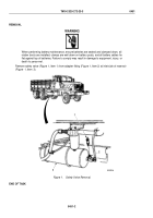
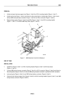
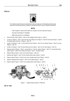
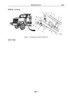
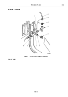
Disconnect two wires (Figure 1, Item 4) from stoplight switch (Figure 1, Item 3).
2.
Loosen nut (Figure 1, Item 7) and remove cross fitting air line (Figure 1, Item 8) from elbow (Figure 1, Item 6)
on double check valve No. 5 (Figure 1, Item 13).
3.
Loosen nut (Figure 1, Item 11) and remove air line (Figure 1, Item 10) from elbow (Figure 1, Item 12) on tee
(Figure 1, Item 13).
4.
Loosen nut (Figure 1, Item 15) and remove air line (Figure 1, Item 14) from tee (Figure 1, Item 13).
5.
Remove locknut (Figure 1, Item 2), screw (Figure 1, Item 6), washer (Figure 1, Item 17), and double check
valve (Figure 1, Item 9) from frame rail (Figure 1, Item 1). Discard locknut.
6.
Remove elbow (Figure 1, Item 12) from tee (Figure 1, Item 13).
7.
Remove tee (Figure 1, Item 13) from double check valve (Figure 1, Item 9).
8.
Remove elbow (Figure 1, Item 6) from end of double check valve (Figure 1, Item 9).
9.
Remove stoplight switch (Figure 1, Item 3) from elbow (Figure 1, Item 5).
10.
Remove elbow (Figure 1, Item 5) from double check valve (Figure 1, Item 9).
1
17
16
13
15
2
3
4
14
12
11
10
9
8
7
6
5
Figure 1.
Double Check Valve No. 5 Removal.
END OF TASK
TM 9-2320-272-23-3
0453
0453-2
Back to Top

