TM-9-2320-272-23-3 - Page 914 of 1469
INSTALLATION - Continued
5.
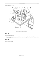
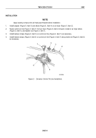
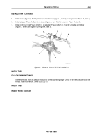
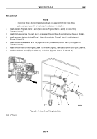
Install elbow (Figure 4, Item 1) on center unloader port (Figure 4, Item 6) on air governor (Figure 4, Item 5).
6.
Install adapter (Figure 4, Item 2) on elbow (Figure 4, Item 1) of air governor (Figure 4, Item 5).
7.
Install control air line (Figure 4, Item 4) on adapter (Figure 4, Item 2) of center unloader port elbow
(Figure 4, Item 1) and tighten nut (Figure 4, Item 3).
4
3
2
5
6
1
M10107DAA
Figure 4.
Governor Control Air Line Installation.
END OF TASK
FOLLOW-ON MAINTENANCE
Start engine and allow air pressure to build to normal operating range. Check for air leaks at control air line
fittings. Road test vehicle. (TM 9-2320-272-10)
END OF TASK
END OF WORK PACKAGE
TM 9-2320-272-23-3
0461
0461-5/6 blank
Back to Top

