TM-9-2320-272-23-4 - Page 1147 of 1393
INSTALLATION - Continued
7.
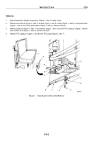
Install two washers (Figure 4, Item 3), screw (Figure 4, Item 4), washer (Figure 4, Item 9), and screw
(Figure
4,
Item
8) on PTO (Figure 4, Item 10) and transmission (Figure 4, Item 2).
8.
Install PTO cable bracket (Figure 4, Item 5) on PTO (Figure 4, Item 10) with washer (Figure 4, Item 6) and
screw (Figure 4, Item 7).
9.
Install PTO cable (Figure 4, Item 16) and PTO cable pin (Figure 4, Item 17) on PTO select lever
(Figure
4,
Item
18) with washer (Figure 4, Item 19) and cotter pin (Figure 4, Item 20).
10.
Install spacer (Figure 4, Item 13) and clamp (Figure 4, Item 15) on PTO cable bracket (Figure 4, Item 5) with
two screws (Figure 4, Item 15) and nuts (Figure 4, Item 12).
TM 9-2320-272-23-4
0728
0728-8
Back to Top


