TM-9-2320-272-23-4 - Page 1154 of 1393
INSTALLATION - Continued
6.
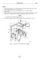
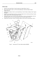
Pull PTO control cable (Figure 4, Item 7) down to PTO from engine compartment and install PTO cable pin
(Figure 4, Item 8) on end of PTO control cable.
7.
Connect PTO cable pin (Figure 4, Item 8) to PTO select lever (Figure 4, Item 9) with washer
(Figure 4, Item 10) and cotter pin (Figure 4, Item 11).
8.
Attach PTO control cable (Figure 4, Item 7) to PTO cable bracket (Figure 4, Item 3) with clamp
(Figure 4, Item 6), spacer plate (Figure 4, Item 4), two screws (Figure 4, Item 5), and locknuts
(Figure
4,
Item
2).
9.
Close transmission dipstick access door (Figure 4, Item 1) inside of cab.
M6109DAA
6
7
8
9
10
11
5
4
3
2
1
Figure 4.
Transmission Control Cable Installation.
END OF TASK
FOLLOW-ON MAINTENANCE
Start engine and check transmission PTO for proper operation. (TM 9-2320-272-10)
END OF TASK
END OF WORK PACKAGE
TM 9-2320-272-23-4
0729
0729-5/6 blank
Back to Top

